APP (1)
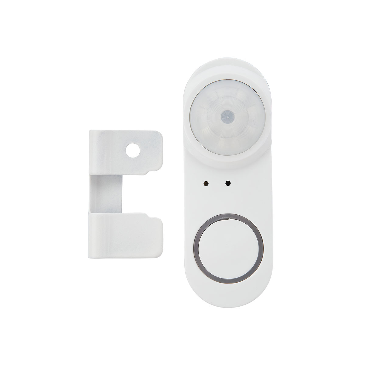
If lights/sensors are not visible in the app after deleting from a Zone, it is necessary to reset the light/sensor. There is a reset hole that a paper quip can be inserted for 3 seconds. The light/sensor will begin to flash to indicate it is reset to factory settings. See https://www.litetrace.com/videos/ for more assistance.
Hardware (38)
Reese’s Law (P.L. 117-171) applies to consumer products and are intended to prevent children from hazards of ingesting batteries in products such as keyless entry remotes, wireless game controllers, toys, and musical greeting cards.
LiteTrace does not manufacture any products that we feel meets the definition of consumer product as defined in the Consumer Product Safety Act. None of our products are sold to consumers for use in or around the household.
The Consumer Product Safety Act (CPSA) defines a consumer product as any article, or component part thereof, produced or distributed for sale to a consumer for use in or around a permanent or temporary household or residence, a school, in recreation, or otherwise.
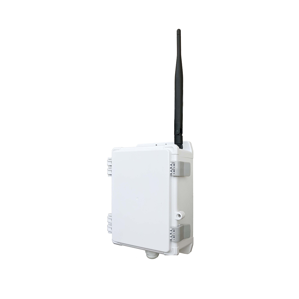
Yes, the 1dB and 5dB external antenna options are interchangeable on Keilton products.
You can swap them depending on your wireless range needs, since they screw on to the same type of connector.
To change antennas:
Unscrew the existing antenna by turning it counter-clockwise to detach it from the product.
Screw on the new antenna by turning it clockwise until it is securely attached.
Tighten firmly but do not over tighten. The antennas only need to be finger-tight.
That’s all there is to it! No other changes are needed when swapping antenna types.
This flexibility allows you to test out the different antenna gains and radiation patterns to determine which works best for your particular installation site. The modular design makes it easy to change them on any Keilton devices with external antennas.
Not at this time. Remote connectivity for troubleshooting and support is on our roadmap, but has not been released yet.
We understand the benefits of being able to remotely diagnose and resolve issues. This would allow support teams to efficiently assist customers without requiring an on-site visit.
While remote access is not possible today, we are actively developing this for a future product update. We don’t have an exact timeline to share yet.
Please stay tuned to our website and other channels for the latest information on new Keilton features. Providing remote troubleshooting access is an important capability we are working toward.
Keilton products designed for ceiling cavity installation carry UL723 or ASTM E84 plenum certification and comply with relevant fire safety standards.
*This rating means they are constructed from materials suitable for use in HVAC plenum spaces.
*They have high flame spread and smoke development safety ratings.
Check individual Keilton product datasheets for details on applicable plenum certifications.
Yes, the IWS102 or any Keilton+autani Bluetooth switch can provide ON/OFF control to any device that is plugged into the controlled portion of the WF20R receptacle.
The steps to facilitate this are:
- Commission the IWS102 to same Zone as the WF20R is on.
- Create a Group and add both IWS102 and WF20R to same Group.
- Enable motion sensing for either Occupancy or Vacancy mode.
- Enable Linkage.
- Set desired time-outs for T1/T2.
- Set “hold time” equal to T1
When the ISW102 triggered, it will turn on the controlled receptacle of the WF20R and off after motion times out. User may also press the ON/OFF button on the IWS102 to turn on the receptacle.
It depends on the open voltage of the DC power supply.
If the open voltage is 12VDC or less, hot swapping should be safe for the devices. However, some DC sources have higher open voltages above 12V (e.g. 36V, 48V). In that case, hot swapping can damage the sensors or exceed their voltage tolerance.
To summarize:
*With a 12VDC or lower open voltage supply, hot swapping is okay.
*If the power supply has an open voltage higher than 12VDC, do not attempt to hot-swap devices while energized.
*Check the exact open voltage of your DC source before attempting hot plug replacement.
The key factor is the uncontrolled open voltage when not loaded – this can spike beyond device limits if higher than 12V. To be safe, fully de-energize the circuit before swapping low-voltage Keilton devices.
Yes, you can disable the motion sensor, photo sensor, or both in the Keilton app. This allows you to use each sensor separately if desired.
Here are some tips on using each sensor independently:
Motion Sensor:
Has a 120-degree coverage area downward from the sensor location.
To fully monitor a large area, install multiple lights and divide them into groups based on room function.
Enable group linkage in the app so lights work in unison.
Set appropriate Timer1 and Timer2 values based on how long the customer wants the lights on after motion is detected.
Photo Sensor:
Measures ambient light and dims lights up/down to maintain desired brightness.
Disable the motion sensor and enable a photo sensor only for lights in areas with adequate natural light.
The photo sensor will keep the lights at optimal brightness throughout the day as sunlight changes.
With the flexibility to enable each sensor separately, you can configure the optimal automated lighting setup for any area. Just be sure to install enough lights and divide them appropriately based on room use. The app makes it easy.
PPA109S as the input dry contact.
The ‘External test button’ wires from PPA109S can be used as ‘Dry contact’ input to the mesh network. Here is how it works:
- Provide power supply to both the normal and emergency power inputs to PPA109S. If this PPA109S is simply used for dry contact input and not for emergency control, then you may connect both inputs to the mains.
- Connects the ‘External test button’ wires from PPA109S to the 3rd party system’s dry contact output, make sure this is a dry contact output, otherwise PPA109S may be fail if, for example, connected to a line voltage to the ‘External test button’.
- Configure the PPA109S
- Upon failure of normal power: this is the action when the dry contact is closed.
- Upon restore of normal power: this is the action when the dry contact is open.
A few typical applications of this include:
- Connect PPA109S to access control systems, so when someone opens a door, the lights turn on.
- Connect PPA109S to fire alarm system so when a fire alert is on, all lights are turned on.
- Connect PPA109S to sercurity system so when an intruder is detected, lights are turned on.
Yes, Keilton’s sensors support both “Occupancy Mode” and “Vacancy Mode” for automatic lighting control.
Here is an overview of how to configure each mode:
Vacancy Mode:
*Lights default to OFF when entering an area
*User must press a switch to turn lights ON manually
To enable:
*Do not enable motion sensing
*Use switches to control lights
Occupancy Mode:
*Lights turn ON automatically when motion detected
*Lights stay on as long as motion continues
*Lights turn OFF after a time delay when no motion detected
To enable:
*Enable motion sensing
*Set desired ON and OFF time delays
*Dim lights to 0% when turning OFF to keep in occupancy mode
The key is that Occupancy Mode requires motion sensing enabled, along with appropriate time delays set for the application.
Dimming lights to 0% vs. toggling power when turning off also keeps the lights in an automatic occupancy control state.
Yes, the CS107D occupancy sensor can be configured to provide “Vacancy Mode” control:
Here are the steps to set up Vacancy Mode with the CS107D:
Commission lights, CS107D sensor, and wall switch to a Zone in the app.
Group the lights into Group 1 (G1).
Enable motion sensing for G1. Set appropriate T1, T2, and dimming levels.
Bind CS107D to G1. Set “Triggered By” to “None” and configure other parameters. Set “Hold Time” = T1.
Bind wall switch to G1.
Daily Operation:
Lights default to OFF. User must press switch to turn ON manually.
CS107D will hold lights ON when occupancy detected.
After T1, lights dim down. After T2, lights turn OFF until switched back ON.
Pressing “AUTO” button on switch returns lights to full programmed state.
So in summary, with Vacancy Mode the lights default OFF and require manual activation. The CS107D holds the lights on while occupied. This differs from Occupancy Mode where lights automatically turn on when motion detected
Yes, Keilton sensors undergo functional testing at our factory before being packaged and shipped.
Our quality control procedures include:
*Individual testing of each produced sensor to verify proper operation
*Calibration and validation of detection accuracy
*Checks for physical defects
*Confirmation of wireless connectivity and pairing
*Simulation of real-world operating conditions
Every sensor is put through this battery of tests to ensure it is performing as designed. Only products passing these inspections are approved for shipment.
Rigorous in-house testing allows us to guarantee the quality and reliability of Keilton sensors. Customers can be confident they are receiving fully-validated products ready for installation right out of the box.
Yes, the Keilton lighting control system retains all configuration settings and commissioning data even during complete power loss or electrical outages thanks to built-in non-volatile memory in the devices.
This memory persists in the configured data whether the power disruption is from:
*Temporary power outage
*Circuit breaker reset
*Device reboot/restart
*Full disconnect from power
When power is restored, the devices will resume operation in their last configured state. No re-programming or commissioning is required after an outage.
Some examples of data retained in non-volatile memory:
*Project bindings and topology
*Grouping and zones
*Sensor settings
*Schedules
*Scenes
*Device names
*Control behaviors
So you can have confidence that a power interruption will not reset or wipe out your configured system. The onboard non-volatile memory retains all commissioning data to withstand power cycling.
The PPA109’s wireless signals can reliably traverse a maximum of 4 hops between devices in a project’s mesh network.
A “hop” refers to the signal jumping from one device to another. For example:
PPA109 >> Light (1 hop)
PPA109 >> Light >> Light 2 (2 hops)
PPA109 >> Light >> Light 2 >> Light 3 (3 hops)
After 4 hops, signal attenuation becomes too high, and relay reliability greatly decreases.
Recommendations:
*Design projects so that any device is within 4 hops of a PPA109 or other controller
*Strategically place lights to ensure robust mesh network coverage across the space
*Keep critical control sources like switches/sensors within a 4-hop radius
Following the 4 hop best practice prevents communication breakdowns between devices that are too many relay points apart in the mesh network. This ensures reliable transmission across even large-scale lighting installations.
Here are two methods to reset LiteTrace devices back to factory default settings:
Using the App:
* Go to the “Lights” page in the app
* Tap the “-” symbol in the top right
* Select the light(s) you want to reset by checking the circle at bottom right corner of Light Icon
* Tap “Delete” in the top right
* Confirm you want to delete the light(s)
This will remove the lights from the “Lights” page and put them back on the “Not Added” page to be re-commissioned
Manual Reset:
* Locate the reset button on the back on the sensor or load controller
* Press and hold the reset button for 3+ seconds until the LED blinks
* This will clear all settings and revert the sensor to factory defaults
* You can now re-commission the sensor through the app like new
The key is to either remove the device from the app or perform a manual reset via the button to wipe its programmed settings. This allows the device to be set up again as if it was new.
To collect energy consumption data and generate an energy report, you require a CR01 energy monitoring dongle. The CR01’s features are as follows:
- It is powered by a USB-A receptacle.
- It has an embedded Real time Clock (RTC) to synchronize time for all devices in the zone, including an internal battery to maintain time during power outages.
- It records the energy consumption raw log onto a SD card.
For more detailed information, please consult the CR01 Specification.
Keilton+Energy+Monitoring+Instruction.pdf
The CR01 records the energy consumption raw log for every device in the zone at 15-minute intervals. In a zone with 100 controllers, it will produce approximately 28 Megabytes of data per month.
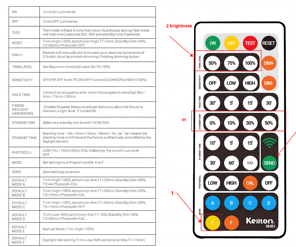
Select the MODE E and select a brightness. PIR and Photocell will at that point be disabled.
- Open the Motion Sensor Testing function on the More page.
- Select “Start Testing”.
- Open the Lights page.
- Walk around under the sensors in question.
- The lights icon will indicate “ON” when you are near the sensor.
- This will identify the sensor and the associated icon in the app.
- Then press and hold the icon till the “Light Dimming” page opens.
- Rename the sensor. Suggest using naming to indicate location, i.e., room number or room name.
- Open the Groups page.
- Add the sensor to the group of lights you wish to control.
- Select the “Light Bulb” icon in the group and then select the “Motion” setting button on lower right-hand corner and choose the settings for your group.
- Select “Save” when complete.
Here is an overview of how we handle warranty issues for Keilton products:
*Keilton provides a standard 5-year limited warranty on most products. See specific datasheets for warranty terms.
*If a product fails during the warranty period, customers can initiate a claim by contacting Keilton Support and providing proof of purchase.
*Our support team will first aim to resolve issues through troubleshooting and sending replacement parts as needed.
*If a product requires return/repair, Keilton will provide an RMA number and process for sending the item to our facility.
*We have dedicated technicians that thoroughly test returned products to determine if the issue is a valid warranty claim.
*For valid claims, we will repair or replace the item free of charge, then ship it back to the customer. Invalid claims are sent back unrepaired.
*Expedited shipping options are available for urgent requests at customer expense.
*Documentation on warranty scope, process, and policy is available on our website and in product manuals.
* The maximum sinking current of LiteTrace’s luminaire-mounted sensors is 10mA. This limits the number of fixtures that can be wired to and dimmed from a single sensor.
* To control a group of lights from one sensor, the FA102 or PPA102S Bluetooth nodes can be added to each individual fixture.
* The FA102 requires a dim-to-off capable driver with 12V AUX output in each light. It allows dimming control.
* Using these Bluetooth nodes distributed on each light allows a single LiteTrace sensor to control multiple fixtures, with the 10mA current draw limit per sensor still applying.
* This distributed Bluetooth architecture allows for grouping multiple lights under one sensor.
So, in summary, current limits define how many lights can be controlled per sensor, with various options available to suit different installation needs.
Here are some optimized guidelines for properly spacing PPA109s for emergency lighting projects:
PPA109 Density Recommendations
*Maintain a maximum 100:1 ratio of light controllers to PPA109s – Install at least 1 PPA109 for every 100 lights.
*For commercial spaces, install 1 PPA109 per 200 square feet of coverage area.
Examples:
*1-100 lights = Minimum 1 PPA109
*101-200 lights = Minimum 2 PPA109s
*10,000 sq ft space = Approximately 10 PPA109s (at 200 sq ft spacing)
Goals:
*Keep all fixtures within reliable wireless range of a PPA109 (max 100:1 ratio)
*Provide overlap between PPA109s for redundancy (200 sq ft spacing)
Properly distributing PPA109s using these spacing guidelines ensures robust mesh network coverage across the entire emergency lighting installation.
Here are some tips for installing and configuring large projects with 100+ lights:
Planning:
*Divide the installation area into smaller sections based on room layout and lighting design. Keep each section under 100 lights.
*Plan lighting circuits based on load capacities and room divisions. Lights on the same circuit should be in the same section. Large sections can have multiple circuits.
Installation:
*Turn-on power separately to each circuit as you commission. This simplifies the commissioning process..
*Only power on one section at a time when configuring in the app. Complete all programming for that section before moving to the next. Avoid powering everything on at once.
*Use the “Sort by Signal” option when adding lights. This arranges them by distance to your mobile device, which helps locating.
*Create the necessary zones, groups, scenes, etc. in the app ahead of time to save on-site time.
*Name everything logically based on room names/numbers to keep organized.
By dividing into smaller sections, configuring one section at a time, and planning ahead in the app, installing large projects with hundreds of lights is manageable. Just take it one step at a time.
If lights/sensors are not visible in the app after deleting from a Zone, it is necessary to reset the light/sensor. There is a reset hole that a paper quip can be inserted for 3 seconds. The light/sensor will begin to flash to indicate it is reset to factory settings. See https://www.litetrace.com/videos/ for more assistance.
LiteTrace uses a proprietary private Bluetooth mesh system. LiteTrace’s proprietary Bluetooth mesh networking protocol offers advanced features custom-designed to optimize performance for our products. These include ultra-low latency for time-critical device coordination and dynamic power management for battery-powered nodes. While proprietary, our mesh has an open API to enable third party devices and apps to interface with the network. We provide documentation and support to foster an ecosystem of compatible products and services. The proprietary technology allows us to innovate while the open API creates flexibility to connect new solutions.
Keilton’s smart lighting system uses Bluetooth technology for wireless communication which indeed operates on the 2.4GHz frequency band.
However, Bluetooth is not directly compatible with other devices that also use the 2.4GHz frequency, like WIFI routers or 2.4GHz RF devices. This is because those technologies use different communication protocols over 2.4GHz.
Here are some key points about Bluetooth vs. other 2.4GHz wireless:
*Bluetooth is its own protocol and not directly interchangeable with WiFi, Zigbee, etc. even though they operate on the same band.
*Bluetooth has mechanisms like frequency hopping to minimize interference from other 2.4GHz signals. But performance can still degrade in noisy environments.
For best results, minimize 2.4GHz interference by not placing devices next to WiFi routers, microwaves, etc. Spread devices out.
Here are the key differences between the 1dB and 5dB external antennas:
Gain – The 5dB antenna has higher gain, meaning it can focus the wireless signal in a narrower beam for increased range. The 1dB antenna has lower gain.
Directivity – The 5dB antenna’s radiation pattern is more focused and directional due to its higher gain. The 1dB antenna is less directive with a wider beamwidth.
Range – The higher gain 5dB antenna can achieve longer transmission distances. The lower gain 1dB antenna has a shorter effective range.
Coverage Pattern – The 1dB antenna provides a broader, multi-directional coverage area. The 5dB antenna’s coverage is more concentrated in a single direction.
Size – The 5dB antenna is physically larger to accommodate the larger reflectors/directors needed to produce the increased gain. The 1dB antenna is more compact.
In summary, the 5dB high-gain antenna is better for long range point-to-point links, while the 1dB antenna is preferable for broader short-range coverage. The choice depends on your specific wireless range and coverage requirements.
The battery life is based on 20 presses per day.
Most batteries have a 10yr shelf life.
The CR2032 capacity has a big range between brands. Duracell is 100mAh while Nanfu is 210mAh capacity.
The AAA capacity is 1800mAh and would offer a much longer life.
- For the Duracell CR2032 (100mAh):
- At 20 presses per day, the battery would theoretically last about 7.3 years until reaching 50% capacity
- Effective life is 7.3 years (limited by capacity depletion)
- For the Nanfu CR2032 (210mAh):
- Would theoretically last about 15.3 years until reaching 50% capacity
- Effective life is 10 years (limited by shelf life)
- For the AAA battery (1800mAh):
- Would theoretically last over 130 years until reaching 50% capacity
- Effective life is 10 years (limited by shelf life)
This confirms that the effective life would be around 10 years for both the Nanfu CR2032 and AAA batteries due to shelf-life limitations, while the Duracell CR2032 would be limited by its capacity to about 7.3 years.
Here are the key points on operating parameters for Keilton DC sensors:
- Ripple voltage on the 12VDC auxiliary power supply should ideally be less than 50mV peak-to-peak. Lower ripple indicates good driver quality.
- Ripple waveform shape, dimming depth to 1%, dimming on/off threshold below 0.1V, linear output, and no flashing/strobing are also important parameters.
- No ripple current feedback from dimming or ground wires back to the sensor.
- Comprehensive testing with the fixture, sensor, and driver properly installed together is recommended for any specific driver model to ensure compatibility.
- Most good quality LED drivers have 12VDC auxiliary ripple less than 200mV, which should work well.
In summary, ripple voltage under 50mV is optimal but less than 200mV is generally acceptable. A smooth ripple waveform along with proper dimming performance, linear output, and no current feedback are also critical for reliable sensor operation. Thorough testing of any particular driver is best to confirm performance.
CR2032 Switch Benefits:
- More compact and slimmer design
- Better for space-constrained installations
- Typically lighter weight
- Excellent shelf life: 8-10 years (lithium-based)
- Performs better in a wider temperature range
2xAAA Switch Benefits:
- Longer operational battery life (2-3x the capacity of a CR2032)
- Less frequent battery changes needed
- AAA batteries are commonly available in most stores
- Easier to replace than the coin cell
- Moderate shelf life: 5-7 years for alkaline AAAs (less for heavy-duty/zinc-carbon)
- Lower self-discharge rate for lithium AAAs if those are used
The CR2032’s superior shelf life means the switch will likely work even after sitting unused for extended periods. This can be particularly valuable for:
- Switches in rarely used rooms
- Backup switches
- Places with intermittent use
If you plan to install the switch in a location where it might go unused for long periods, the CR2032 option has a distinct advantage due to its longer shelf life and lower self-discharge rate. However, if the switch will see regular use, the operational capacity advantage of AAAs may outweigh the shelf life consideration.
Here are some optimized recommendations for connecting a remote test button to PPA109S over long distances:
For spans up to 500 feet between the test button and PPA109S, we suggest the following:
*Use 14 AWG or 12 AWG wire for the button connection. The larger wire gauge minimizes voltage drop over long cable runs.
*Install a dry contact relay near the test button, then use a thinner gauge wire from the relay to the PPA109S. This allows the relay to isolate and extend the contact over greater distances.
The key goals are:
*Maintain strong signal integrity from the button to the PPA109S.
*Avoid excessive voltage drop through thinner gauge wires over long cable lengths.
By using a heavier gauge wire or remote relay, you can reliably connect test buttons to PPA109S located up to 500 feet away.
What is firmware?
Firmware is the permanent software that lives inside each piece of hardware.
Think of firmware like the operating system on your smartphone. Just as Apple and Google regularly update iOS and Android to add features, fix bugs, and maintain security, we update our firmware to ensure your lighting system stays current, secure, and compatible with new capabilities.
Our firmware is the ‘brain’ of your hardware. It tells the device how to function, how to respond when you press a button, how to communicate with your phone app, how to dim a light, or how to detect motion. When we don’t update it, you’d miss out on new features, performance improvements, and important fixes
Firmware vs. Apps
| Mobile App | Firmware |
| Lives on your phone/tablet | Lives inside each hardware device |
| Updates through App Store | Updates through the app to the device |
| One app controls many devices | Each device has its own firmware |
| Interface you see and touch | “Brain” you never see |
Each Device Has Its Own Firmware
This is important: each piece of hardware in your system has its own firmware. Your occupancy sensor has one firmware version, your gateway has another, and your dimmer switch has yet another. That’s why when you see an update available, it might only be for specific devices, or why updates might take time. We’re updating multiple ‘brains’ in your system.
Why It’s Called ‘Firmware’
It’s called ‘firm’ ware because it sits between:
- Hardware (physical/permanent – the circuits and chips)
- Software (flexible/temporary – your mobile app)
It’s more permanent than software but more updateable than hardware.
Why does firmware sometimes need to be updated?
- New Features: Updates enable capabilities that didn’t exist when you first purchased
- Bug Fixes: We constantly improve reliability based on real-world feedback
- Compatibility: As apps and platforms evolve, firmware must keep pace
- Security: Like any connected device, security patches are essential
- Cost-Free Improvements: Unlike buying new hardware, updates enhance what you already own
The CS107D is designed for ceiling heights of 8-10 feet. At 12-14 feet and above, detection performance will start to decline.
The key factors are:
*The sensor’s infrared technology is designed and calibrated for 8-10 foot ceiling height. This ensures accurate presence and vacancy sensing in typical applications.
*At increased heights beyond 12-14 feet, the sensor’s field of view expands, resulting in reduced sensitivity and potential detection gaps.
*High ceilings also introduce more ambient temperature variations that can interfere with performance.
While the CS107D may still function in some limited capacity at heights above 14 feet, detection reliability and coverage area will be compromised.
For ceilings higher than 12-14 feet, we recommend considering a higher power, long-range sensor specialized for large open spaces.
For more info, see CS107D Instruction Sheet. http://keiltonmanual.s3.amazonaws.com/Instruction-CS107D.pdf
Our testing has shown the PPA109 can reliably control lights at distances of up to 15 meters (49 feet).
15 meters is not the absolute upper limit, but we recommend maintaining a distance of 15 meters or less between a PPA109 and the lights it controls for optimal reliability.
Factors that can affect maximum distance include:
*Obstructions between the PPA109 and lights
*Building materials that interfere with wireless signals
*Highly congested wireless environments
Under ideal conditions, PPA109s may be able to reach further than 15 meters. However, limiting the distance to 15 meters or less helps ensure consistent communication and control.
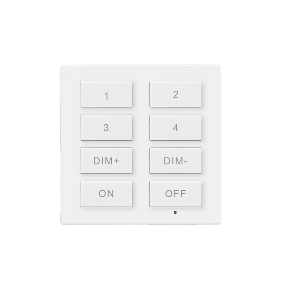
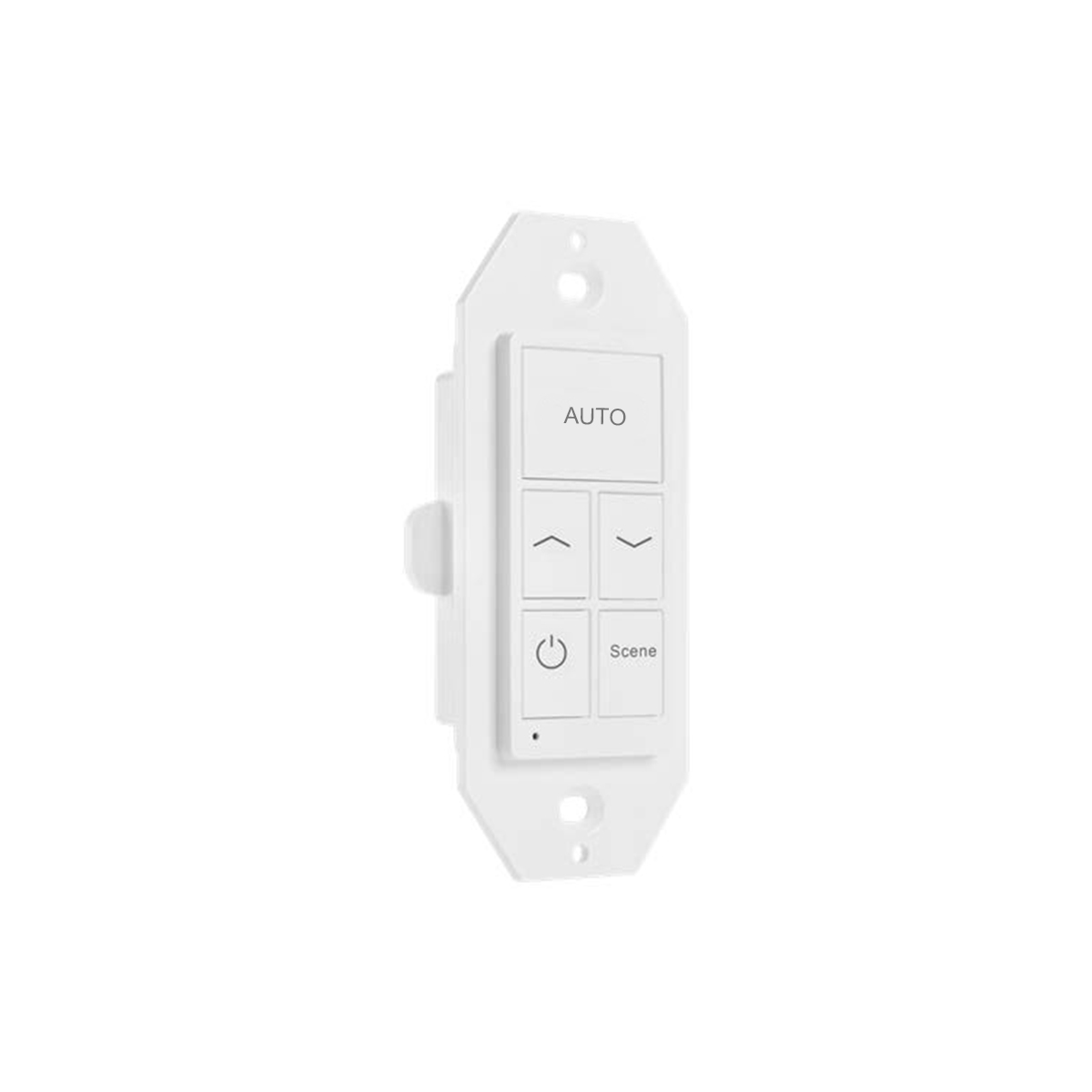
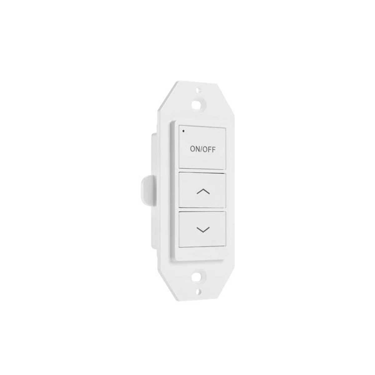
Bluetooth wall switches use the same wireless technology as the lights. When idle, the switches are powered off to conserve energy. They transmit signals only when pressed.
The BT transmission range is similar to the lights – up to 50 meters (164 ft) indoors. However, for the best user experience, it is recommended to install panels within 20 meters (66 ft) of the nearest controlled lights.
Here are some guidelines on transmission distances:
*Maximum distance between the switch and lights it directly controls: 20 meters (66 ft)
*Farthest distance lights can be from the switch and still receive signals: 200 meters (656 ft)
*Lights beyond 200 meters may not receive switch signals reliably
*The 200 meter total transmission range allows flexibility in lighting layouts. You can control distant lights by placing panels strategically within that radius.
Following these distance recommendations allows reliable communication between the wall switches and lights for the best user experience.
If your lights have built-in sensors, they will automatically dim to a preset level when first powered on rather than going to 100% brightness.
Here’s why:
The sensors detect ambient light levels in the room and dim the lights accordingly to maintain the desired brightness.
The light is programmed to turn on at a preset dimming level that is less than 100%. This prevents lights from being overly bright when first turned on.
Photo sensors will automatically raise or lower the dimming level based on the amount of natural light in the room.
So in most cases, the lights will not immediately go to maximum brightness when powered on or turned on from the app or a scene. The sensors modulate the dimming level upon startup for a more comfortable experience.
You can override this by manually setting the lights to 100% brightness after startup if desired. But letting the sensors control the initial dimming often provides a better experience.
RP0 is a signal booster and it requires very little power consumption during when it is powered on, less than 20mA. Some power bank detects the output current and will shut the output off if output current is very small. That was what happened in this case.
Please find a power bank that can keep constant power output.
For example, this ROMOSS power bank: https://a.co/d/jhVyrz6 has a button to turn on / off the output on the side, when double click this button, it will enter the ‘constant output’ mode and keep the RP0 working. You may check whether your power bank has the same function, or use the ones that have this ‘constant output’ mode.
There are a few reasons we put BCS107 in switch page:
It is battery powered.
User must press a button to set it to pairing mode to commission it.
It is not counted in 100-device limit.
These features make BCS107 more like a switch rather than an ‘Area sensor’ such as CS107D. Both APP and firmware of BCS107 works in the same logic of switch too.
| CS107 / BCS107 commission comparison | ||
| CS107D/CS107S | BCS107 | |
| User interaction | Goto ‘Discover’, ‘Area Sensors’ page.Click ‘+’ to start adding area sensors.APP list all factory setting area sensors available.User confirm which area sensors should be commissioned to current zone, select, and check those icons.Click ‘Add’ button on APP to start adding those selected sensors.Wait for APP to complete, confirm the result and re-try if necessary. | Goto ‘Discover’, ‘Switch’ page.Click ‘+’ to start adding BCS107.Press and hold the button on BCS107 for 3 seconds and then release it.Wait until APP shows 1 device has been commissioned. |
| APP | APP searches for factory setting area sensors, list them for user to select, then wait for user’s command and only commission those have been checked. | APP searches for factory setting BCS107 and immediately commission them without user’s further confirmation. |
| UI | ||
| Others | User may use FlashNet to quick commission CS107D/S.User may enable / disable BLE signal of CS107D/S to help commission. | BCS107 will exit commission mode and restore previous mesh network setting after 30 seconds.No FlashNet compatible.No enable / disable BLE signal feature. |
PPB102 is a phase dimmer. It can select the forward-cut or reverse-cut function by means of a dip switch, typically works with standard incandescent loads because these loads are resistive and can handle the waveform modifications created by phase cutting. However, when it comes to Electronic Low-Voltage (ELV) transformers, the compatibility is more complex.
ELV transformers are designed to work with electronic dimmers, specifically leading-edge or trailing-edge dimmers, depending on the transformer design. Forward-cut dimmer may not be compatible with ELV transformers because they can cause flickering, buzzing, or improper operation. ELV transformers usually require reverse-cut dimmers, which are better suited for their electronic nature.
If you intend to use PPB102 with an ELV transformer and low-voltage incandescent loads, ensure PPB102 is in the reverse-cut function mode. Always check the compatibility of the PPB102 with the transformer and load to avoid damage or improper performance.
Keilton APP (37)
The ‘pseudo switch’ on the ‘Switch’ page of the APP is only for illustration, the ‘ON/OFF’ button on the APP acts different from the physical button on the switch. The ‘ON/OFF’ button: • ‘ON’ button on the switch sends ID to the sensors, sensor translates it to ‘FULL ON/OFF’ commands. • ‘ON’ button on the APP ‘AUTO/OFF’ commands sensors. It does not send exact ‘button and switch ID’ to sensors.
Products for this application:
A sensor, such as a EFS107 (designated as “E”); A controller, such as a PPA102S (designated as “P”); and a Bluetooth switch such as a WP1013 (designated as “S”)
Configuration Setup:
Join “E”, “P” and “S” in a Zone.
Configure “E” to:
Enable motion sensing. Set to Vacancy mode with T1=Infinite, T2=1, Dim Level=50%, disable Daylight Harvesting (DLH).
Configure “P” to:
Enable motion sensing, Occupancy mode, T1=1, T2=(Fan delay OFF time out), Dim Level=100%, disable DLH.
Create a Group and add “E” and “P” as members. Enable Linkage. Set Linkage brightness at 100%.
Associate “S” with “E”/
Results:
Turn ON the switch when entering the room. This will turn ON the lights and the fan.
When leaving the room, turn OFF the switch and the lights will turn off but the fan will stay ON till the Time-Out delay occurs.
Alternate Configuration:
To have occupancy be automatic, change from the Vacancy mode of “E/P” to Occupancy mode.
Sensors with daylight harvesting can turn off fixtures, when the driver on the fixture will cut off the LED current when 0-10v signal drop down to range of 1%-10%.
Most of outdoor fixture drivers will cut off LED current at 5% to 7% dimming level.
Following are the detailed step-by-step description of the configuration to allow EFS106-DLH sensor to turn on off fixture by daylight harvesting sensors.
1. Prepare: please have a RP0 and powered it on with a proper power bank.
a) Some power banks may cut off power to RP0 because the current is very small, please make sure to the power bank you use can sustain the continue power supply.
2. Set the RP0 to factory setting before commission (press and hold the reset button on RP0 to reset it when necessary) and keep it powered on with you.
3. Create a new zone on you APP, and name it properly.
4. Commission all EFS106-DLH sensors to the zone.
a) Factory setting RP0 can help commission the sensors.
b) You may need to
5. Commission the RP0 to the zone, and keep it powered on and with you after commissioned it.
a) You need to commission the RP0 from “More”, “Device Info” page on the APP. Factory setting RP0 will show up in ‘Add lights’ page but you won’t be able to commission it from here.
6. Go to ‘Group’ page, click the dimming button on ‘All Lights’ group, click the sensor setting button to bring out the sensor setting page.
7. Enable ‘Daylight harvesting’, enable ‘Motion’ sensor, set proper T1 (say 20 minutes), set T2 to ‘INFINITE’, set proper Dim evel (say 20%). Then click ‘Save’.
a) You will see fixture flush to indicate it received the command.
8. During the night, go to ‘Group’ page, click the dimming button on ‘All Lights’ group, dim all lights to 100% and click ‘A’ to save the auto point.
9. Dim All Lights to 100%.
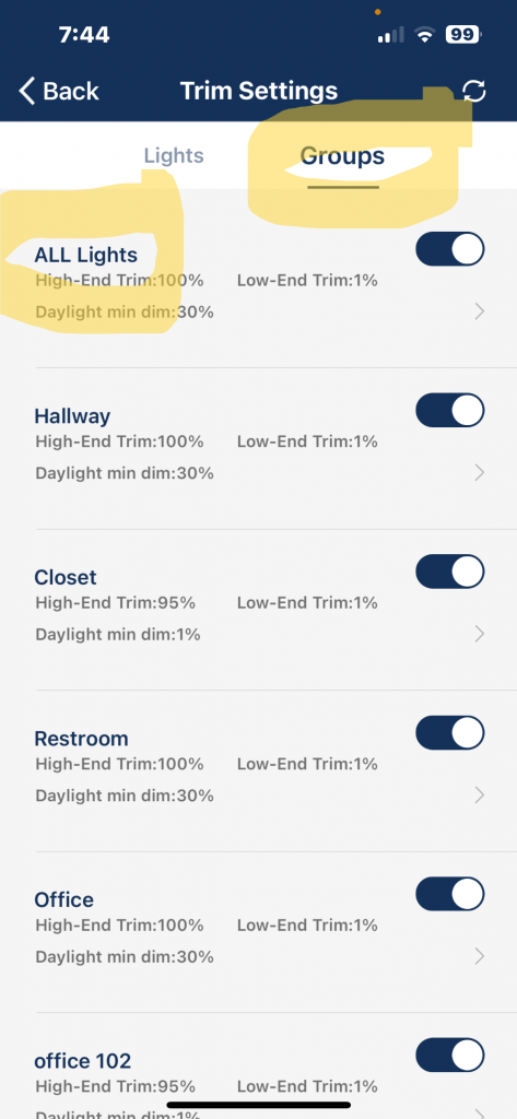
10. Go to ‘More’ page, click ‘Trim Settings’, select “Groups”, click the ‘>’ beside ‘ALL Lights’,
a) Click ‘Low-End Trim’, select ‘1%’, then click ‘Send’ in ‘Low-End Trim’ section.
i. All sensor should dim to 1%, in this case, fixture should be turned off, otherwise, this won’t work.
11. Dim All Lights to 100%.
12. Go to ‘More’ page, click ‘Trim Settings’, select “Groups”, click the ‘>’ beside ‘ALL Lights’,
a) Click ‘Daylight min dim’, select ‘1%’, then click ‘Send’ in ‘Daylight min dim’ section.
i. All sensor should dim to 1%, in this case, fixture should be turned off, otherwise, this won’t work.
Starting from step 6 in the outdoor jobsite, you may need to walk around with RP0, and click “Save” for a few times to make sure all sensors received setting and commands.
Test to confirm:
1. Turn on all lights from APP, then cover the sensor to prevent daylight from coming to the sensor (or test it in the night), fixture should be turn on and dim to 100%.
2. Remove the cover, use a flashlight or other light to direct at the sensor, fixture should dim down and turn off.
3. Test in the night, the fixture should dim down to Dim Level after T1 timed out, and does not turn off. It dim up to 100% when motion is detected.
There is currently no native way to directly control Keilton devices from a desktop or laptop computer.
However, devices can be controlled indirectly using a BLE-485 gateway device connected to your computer.
How it works:
Connect the BLE-485 gateway to your computer via USB
Pair the gateway with your Keilton product using Bluetooth
Install a terminal program on your computer that can send serial commands
Use text commands to turn lights on/off, dim, recall scenes
This setup allows basic unilateral control of lights from a computer. But the mobile app is still required for configuration like creating groups or renaming devices.
Limitations:
No editing of project settings and structure from a computer
Control is one-way only (computer to lights)
Limited to basic textual serial commands
You can easily grant other users remote access privileges to control your project. Here’s how:
In the Keilton app, locate the QR code associated with your project. This QR code contains all the information needed for others to connect to the project.
Save a picture of this QR code to your phone’s photo album.
Share this QR code picture with other users via email or text.
When the remote user receives the QR code picture, they simply open the Keilton app on their own device and scan the QR code.
Scanning the QR code will automatically give the user access to your project with the privilege level you specified when generating the code.
That’s it! By sharing the QR code picture, you can securely give access to your project without needing to share your login credentials. The user just needs to scan the code you provide to gain access.
In most cases no, the Keilton app is designed exclusively for Keilton systems and would not typically be compatible with other brands of lighting hardware or software.
Yes, the IWS102 or any Keilton+autani Bluetooth switch can provide ON/OFF control to any device that is plugged into the controlled portion of the WF20R receptacle.
The steps to facilitate this are:
- Commission the IWS102 to same Zone as the WF20R is on.
- Create a Group and add both IWS102 and WF20R to same Group.
- Enable motion sensing for either Occupancy or Vacancy mode.
- Enable Linkage.
- Set desired time-outs for T1/T2.
- Set “hold time” equal to T1
When the ISW102 triggered, it will turn on the controlled receptacle of the WF20R and off after motion times out. User may also press the ON/OFF button on the IWS102 to turn on the receptacle.
Can the mobile apps (Keilton+autani, Keilton Pro HD, Spiral Engineering) be used on a PC or Laptop
Keilton mobile apps are designed to operate on mobile devices aligns well with field work requirements
At this time, the Kelton apps are available for free download for both iOS phones and tablets and Android phones and tablets. They are not available for use on PC or laptops.
Spiral Engineering which is our app for perfoming over the air firmware (OTA) updates, is only available on iOS platforms.
We continue to develop and improve the use and functions.
There are a few methods to help identify the physical location of an installed sensor:
- Commission sensors individually:
If possible, power off all ceiling sensors, then power on and commission just one sensor at a time and add it to the zone. Name each sensor as it is added to make identification easier. - Connect a non-smart fixture to the CS107 relay output, and turn it on/off to locate CS107:
Use the relay output on the sensor to directly control a standard, non-BT-enabled light.
Test using these steps:
A. Create a group on the zone called G1. No member lights in this group.
In the configuration page, bind the sensor to this G1 group. Set other parameters to proper values as required by the project (be sure to disable the photocell of G1)
B. Trigger sensor and observe response:
Return to the Group page, click the on/off toggle button to turn on/off the G1 group, and identify the CS107 location. Note there will be an audible click to help identify the relay. - Bind the CS107 with another sensor/controller. Turn on/off to locate CS107
CS107 can turn on other Keilton sensors and controllers.
Test using these steps:
A. Create a group in the Zone called G1. Add a sensor or controller to the group called L1.
Enable motion sensor function for group G1
B. In the CS107 configuration page, bind G1 to CS107. Set other parameters to proper values as required by the project (be sure to disable the photocell of G1)
C. Turn on G1. On the ‘More’ page, click ‘Motion Sensor Test’ (L1 should be turned off)
Wait a few seconds, then try to trigger the CS107 to find out which device activates L1 - Check Nearby Devices
Use the ‘Nearby Lights’ function in the app and walk below the sensor. Refresh nearby devices until the sensor appears with the strongest RSSI (negative number closest to 9). This indicates you are closest to the sensor’s physical location.
“When you click ‘More’ at the bottom of the screen, click ‘Nearby Lights’. On this page, on the top right of the screen you will find ‘Type Rev’
For each device ID, the numbers shown on the top row represent the firmware rev. (example 0x68-20). The numbers shown on the second row indicate the firmware date code (example: 221103 = November 3, 2022)
When you click ‘More’ at the bottom of the screen, click ‘Nearby Lights’. On this page, on the top right of the screen you will find ‘ID RSSI’.
The device ID with the lowest number is typically the strongest signal and may be the closest device to the user.
To collect energy consumption data and generate an energy report, you require a CR01 energy monitoring dongle. The CR01’s features are as follows:
- It is powered by a USB-A receptacle.
- It has an embedded Real time Clock (RTC) to synchronize time for all devices in the zone, including an internal battery to maintain time during power outages.
- It records the energy consumption raw log onto a SD card.
For more detailed information, please consult the CR01 Specification.
Keilton+Energy+Monitoring+Instruction.pdf
The CR01 records the energy consumption raw log for every device in the zone at 15-minute intervals. In a zone with 100 controllers, it will produce approximately 28 Megabytes of data per month.
- Open the Motion Sensor Testing function on the More page.
- Select “Start Testing”.
- Open the Lights page.
- Walk around under the sensors in question.
- The lights icon will indicate “ON” when you are near the sensor.
- This will identify the sensor and the associated icon in the app.
- Then press and hold the icon till the “Light Dimming” page opens.
- Rename the sensor. Suggest using naming to indicate location, i.e., room number or room name.
- Open the Groups page.
- Add the sensor to the group of lights you wish to control.
- Select the “Light Bulb” icon in the group and then select the “Motion” setting button on lower right-hand corner and choose the settings for your group.
- Select “Save” when complete.
If a light/sensor is not connected in the Zone then you must reset the device by either pressing the reset button on the device (see product instructions) or perform a manual ON/OFF sequence operation. The steps are:
- Confirm all lights are off.
- Turn on lights for 8 seconds; then turn the power off for 10 seconds.
- Immediately turn the lights on and off, then wait for another 10 seconds. Repeat 3 times.
- Turn the lights on for 8 seconds, then turn the power off for another 10 seconds. Repeat 2 times.
- Turn the lights back on. Blinking Lights indicate a successful factory reset. All previous settings and data for these lights have now been deleted. Waiting for at least 10 seconds will ensure that the fixture is completely powered off.
The duration will vary depending on the driver and the power supply. If the driver can cut power to the fixture within 3 seconds, then you may change the waiting period from 10 to 3 seconds to facilitate a faster reset time.
A maximum of 100 lights can be in a single ZONE.
The maximum number of phones that can simultaneously control the lights is limited by the number of online devices in the project.
For example, if there are 10 lights actively online, then up to 10 phones can connect and control the lights at the same time. Each phone needs an individual online device to grant access.
Please note the app still occupies the Bluetooth connection even when running in the background. To allow a new phone to connect, completely force quit the app on the first phone to fully release the Bluetooth connection.
Important: Do not perform editing operations like adding, deleting, or modifying lights, scenes, or groups from more than one phone simultaneously. This can lead to data corruption. Only one phone should edit project details at a time.
The Keilton app is typically updated approximately once per month.
These releases include:
*New features, functionality, and improvements
*Bug fixes and issue resolutions
*Performance enhancements
Though the cadence can vary, our aim is to push major app updates on a monthly basis. This allows us to continuously expand capabilities, while also addressing any problems or stability concerns promptly.
Users will be notified through the App Store/Play Store when new versions are available. We highly recommend keeping the app up-to-date to take advantage of the latest features and fixes.
Major updates will also be announced on our website and in other communications. Please reach out if you ever have any feedback on the app or suggestions for new capabilities!
LiteTrace Keilton network system will not lose their settings if power is lost. They have non-volatile memory and retain their settings during power interruption.
The user-specified calibration brightness during sensor commissioning does not affect the configured high-end and low-end trim settings.
The high/low end trims set the absolute maximum and minimum light levels allowed. These establish preset boundaries.
The calibration brightness is used to tune the daylight harvesting performance within those trim endpoints.
For example:
High End Trim = 80% (4000 lumens for a 5000 lumen fixture)
Low End Trim = 20% (1000 lumens for a 5000 lumen fixture)
Calibration Brightness = 50% (2500 lumens for a 5000 lumen fixture)
With these settings:
The calibration will tune the daylight dimming to maintain around 2500 lumens.
The light level will never exceed the 4000 lumen high end trim nor drop below the 1000 lumen low end trim.
So in summary, the trims create firm dimming limits, while the calibration tuning happens in between those. The trims remain unaffected.
This provides both guaranteed minimum/maximum light levels as well as tuned automatic daylight dimming based on conditions.
Yes, the Keilton app will automatically update to the latest version once it is released. Users do not need to manually install updates.
When we publish a new version of the app, it will automatically be pushed and installed on your device provided:
*Your device is connected to the internet
*Automatic app updates are enabled in your device settings
*The Keilton app was downloaded from the official App Store/Play Store
Users will receive a notification from the app store when the Keilton app updates in the background. We recommend leaving automatic updates enabled to always have the latest features and fixes.
The auto-update capability means you can ensure you are always running the most up-to-date Keilton app version without any extra steps.
Yes, there is an option to set Trim levels for All Lights in the Zone (Network) under the Groups column. You would need to open each Zone while at the site and connected to the mesh network.
Set the dimming level and CCT setting on the Lights setting page and select ‘A’ button on lower right corner to save the settings.
Switches need to be paired with the lights in the Keilton+autani app. Please see the Keilton+autani App Instructions. Keilton+App+Instruction.pdf Or the Setup Guide
Keilton+Autani+Setup+Guide.pdf
Another reason for them not working outside of the app is the battery has not been installed or is dead. The battery is shipped in same package as switch but needs to be installed.
If you have further issues, contact Technical Support: https://autani.zendesk.com/hc/en-us/requests/newsupport@autani.com
Contact phone: 443-320-2233 (M-F 9am-5pm ET)
Auto Brightness is for sensors with Daylight Harvesting sensors only. It represents the set point light level for the sensor to maintain with daylight present.
There are two main privilege levels on a Keilton project, associated with two distinct QR codes:
Admin Privileges:
*Orange QR code
*Automatically granted to the project creator
*Has full control over the project
*Can add, delete, rename groups, scenes, switches, schedules
*Can modify sensor settings and parameters
*Can perform any operation on the project
User Privileges:
*Green QR code
*Granted when project access is shared with others
*Has limited, read-only capabilities
*Can only dim or turn off lights
*Cannot modify or edit the project
In summary:
*Admins have full control and configuration access
*Users have read-only access to control lights
*Two levels allow granting basic access without full control
When naming a Zone in the APP, only the following characters are allowed: lower case, capital letters, numbers, and following symbols ( . , – : _ + ).
The Keilton app shows a light bulb icon next to each light on the project. This represents the current status of that light.
If you see an “A” inside the light bulb icon, it means that the light is in automatic mode. Automatic mode means the light is being controlled by sensors, not manually.
Here’s what happens in automatic mode:
Sensors detect occupancy and ambient light levels and automatically turn the light on or off as needed.
Lights will automatically dim up or down depending on the sensor readings, without any user input.
The light is essentially controlled by the sensors, not manual inputs.
Once you manually control the light, such as turning it off or setting a scene, it will exit automatic mode and the “A” will disappear from the icon.
So in summary, the “A” indicates a light is currently being automatically controlled by sensors, not manual inputs. It lets you know that light is in automatic mode at a glance.
Received Signal Strength Indicator. RSSI is a measurement of the power level present in a received radio signal. RSSI is used to determine wireless signal strength and quality. It can help troubleshoot connectivity issues.
RSSI is measured in dBm (decibels relative to one milliwatt). Typical values range from -30 dBm (excellent signal) to -90 dBm (very weak signal). The higher the dBm value, the stronger the signal. -30 dBm is a much stronger signal than -90 dBm for example. RSSI measurements fluctuate rapidly, so values typically need to be averaged over time for accuracy. Factors like distance, obstacles, interference, weather, and network traffic can affect RSSI.
Thus, when an RSSI value is represented in a negative form (e.g. −100), the closer the value is to 0, the stronger the received signal has been.
In the Keilton system, when RSSI <= -60 dBm the signal is considered GOOD. When RSSI <= -80dbm the signal is considered ACCEPTABLE.
No, Bluetooth Low Energy (BLE) and Bluetooth Mesh are not the same things. Here’s a breakdown of the differences between BLE, Bluetooth Classic, and Bluetooth Mesh:
1. Bluetooth Low Energy (BLE):
– BLE is a low-power wireless communication protocol designed for short-range communication.
– It operates in the 2.4 GHz ISM band, just like Bluetooth Classic.
– BLE is optimized for low power consumption, making it suitable for battery-powered devices like fitness trackers, smart home sensors, and other IoT devices.
– BLE supports point-to-point connections between two devices, but it does not inherently support mesh networking capabilities.
2. Bluetooth Classic:
– Bluetooth Classic is the original Bluetooth standard, designed for continuous data streaming and higher data rates (up to 3 Mbps).
– It consumes more power than BLE but offers higher throughput.
– Bluetooth Classic is used for applications like wireless headsets, file transfers, and device-to-device communication where higher data rates are required.
– Like BLE, Bluetooth Classic does not inherently support mesh networking capabilities.
3. Bluetooth Mesh:
– Bluetooth Mesh is a separate protocol built on top of Bluetooth Low Energy (BLE) technology.
– Buetoooth Mesh is the technology used in LiteTrace’s Keilton+autani products
– It adds mesh networking capabilities to BLE, allowing devices to communicate with each other in a mesh topology.
– In a Bluetooth Mesh network, devices can relay messages to each other, extending the range and reliability of the network.
– Bluetooth Mesh is designed for creating large-scale, multi-node networks for applications like smart home automation, industrial automation, and asset tracking.
– Bluetooth Mesh introduces additional features like message relaying, self-healing capabilities, and support for multiple simultaneous communication paths.
In summary, BLE and Bluetooth Mesh are not the same. BLE is a low-power communication protocol focused on point-to-point connections, while Bluetooth Mesh is a separate protocol that adds mesh networking capabilities on top of BLE, enabling many-to-many communication and large-scale mesh networks.
Bluetooth Classic is the original Bluetooth standard, designed for higher data rates and continuous data streaming, but it does not support mesh networking capabilities either.
The time from when the button is clicked to when the sensor starts responding is fast at 40 milliseconds (ms). After being triggered, the sensor does not immediately snap the lights on/off. Instead, it gently fades the lights up or down over 500ms. The 500ms fade time provides a smooth and gradual dimming transition, preventing harsh or abrupt light changes. Together, the very fast 40ms trigger response and 500ms fade time allow the system to react instantly to occupancy changes while still ensuring comfortable light dimming. These performance metrics indicate LiteTrace has engineered the system for quick response and optimal user experience.
The Keilton app requires Bluetooth 4.1 hardware or later on your device in order to work properly. This is because the app uses BLE (Bluetooth Low Energy) to communicate with Keilton devices. Phones with Bluetooth hardware earlier than 4.1 will not work correctly.
Apple Devices:
The Keilton app is compatible with most iPhones and iPads using iOS 10 or higher. This covers most iPhone models from the iPhone 5 onwards.
Android Devices:
The app supports Android 5.0 (Lollipop) or newer. It should work on most modern Android smartphones but may have issues connecting on older models or devices with heavily modified versions of Android.
Troubleshooting Tips:
If having connectivity problems, first make sure your device supports Bluetooth 4.1 or later. This can be checked in your phone’s settings. Older Bluetooth hardware is the primary reason the app may fail to operate normally.
Outdated OS versions, custom ROMs, or changes made by device manufacturers can also cause compatibility issues on some Android devices.
The Keilton app saves a QR code image in your photo album when you first create a new project. This code contains the details needed to connect to the project.
If you lose your phone before you have a chance to share the QR code with others, here are some tips:
Regularly back up your QR code images to a safe location like cloud storage or an external hard drive. This ensures you have a copy if your phone is lost. If you can replace the phone for the same account, the QR images should be restored to the new phone once the account is reactivated.
As long as you still have the QR code image file, you can install the Keilton app on a new phone and regain access by scanning the code.
If you completely lost the QR code before sharing it, you will, unfortunately, have to reset all your devices back to factory default settings. Go to FAQs – Litetrace for information on resetting devices. This will remove any existing programming and project configurations. You’ll have to set up your project from scratch again. Another option is to visit the site and open a new app and go to More tab and then open Nearby Lights. Record the Network ID’s shown under the Network name for the devices connected to “Network Unknown”. Then send an email with the information to customer-support@litetrace.com. An effort will be made to locate the QR codes. This requires considerable resources to complete.
To avoid losing access, be sure to back up your project QR codes periodically before sharing them. The codes act as your “key” to access your project if your phone is lost.
The Keilton+autani App is available on the app store. Use these QR codes to download.

It sounds like there are a couple main reasons users may see devices constantly connecting and disconnecting in the app during the commissioning process:
- If there are too many factory-default lights powered on close together, this can overwhelm the app with wireless RF signals as it tries to maintain connections with all the lights broadcasting setup signals simultaneously. The excessive number of lights flooding the network makes it difficult to hold steady connections.
- As the user physically moves around the jobsite during commissioning while holding their phone/tablet, they may walk in and out of range of different devices. This forces the app to lose and reestablish connections as it jumps between communicating with nearer and farther devices.
Additionally, the normal behavior of toggling between the “Lights” and “Added” pages in the app requires switching communication between already commissioned zones versus factory default lights. So, the constant shifting between these modes as part of regular commissioning also leads to a lot of reconnecting.
In summary, dense clusters of factory default lights and user movement during the process can cause a flurry of dropped and reestablished connections as the app tries to keep up. This is expected behavior but limiting the number of lights on at once and commissioning from a fixed location can help reduce the connection churn if it becomes problematic.
The app light status is showing the commanded state, not the actual output. So even if the trim limits the output to 80%, if the user has set the dim level to 100%, the app will show 100% status.
A red dot next to a zone name in the Keilton app can indicate two possible issues:
Low batteries – This means one or more devices in the zone has batteries below 20% and needs replacement. The red dot appears as a low battery warning.
Poor connectivity – The red dot can also appear when a zone has trouble syncing data due to poor project connectivity.
In this case:
*The red dot indicates the zone cannot connect to sync lighting data.
*This is usually caused by an intermittent network issue preventing proper data syncing.
*Once connectivity is restored and sync completes, the red dot will disappear.
There are a few reasons we put BCS107 in switch page:
It is battery powered.
User must press a button to set it to pairing mode to commission it.
It is not counted in 100-device limit.
These features make BCS107 more like a switch rather than an ‘Area sensor’ such as CS107D. Both APP and firmware of BCS107 works in the same logic of switch too.
| CS107 / BCS107 commission comparison | ||
| CS107D/CS107S | BCS107 | |
| User interaction | Goto ‘Discover’, ‘Area Sensors’ page.Click ‘+’ to start adding area sensors.APP list all factory setting area sensors available.User confirm which area sensors should be commissioned to current zone, select, and check those icons.Click ‘Add’ button on APP to start adding those selected sensors.Wait for APP to complete, confirm the result and re-try if necessary. | Goto ‘Discover’, ‘Switch’ page.Click ‘+’ to start adding BCS107.Press and hold the button on BCS107 for 3 seconds and then release it.Wait until APP shows 1 device has been commissioned. |
| APP | APP searches for factory setting area sensors, list them for user to select, then wait for user’s command and only commission those have been checked. | APP searches for factory setting BCS107 and immediately commission them without user’s further confirmation. |
| UI | ||
| Others | User may use FlashNet to quick commission CS107D/S.User may enable / disable BLE signal of CS107D/S to help commission. | BCS107 will exit commission mode and restore previous mesh network setting after 30 seconds.No FlashNet compatible.No enable / disable BLE signal feature. |
LiteTrace (1)
The list of EcoSystem Partners is shown on the LiteTrace website. EcoSystem – Litetrace
Software (6)
Can the mobile apps (Keilton+autani, Keilton Pro HD, Spiral Engineering) be used on a PC or Laptop
Keilton mobile apps are designed to operate on mobile devices aligns well with field work requirements
At this time, the Kelton apps are available for free download for both iOS phones and tablets and Android phones and tablets. They are not available for use on PC or laptops.
Spiral Engineering which is our app for perfoming over the air firmware (OTA) updates, is only available on iOS platforms.
We continue to develop and improve the use and functions.
- BLE4.2 and BLE5.0 are fully compatible with each other. There are no issues with interoperability.
- BLE5.0 is a newer version that offers some advantages such as lower power consumption, which can benefit individual devices like battery powered switches.
- However, to take full advantage of BLE5.0’s features like increased device capacity per network node, all devices on the system need to be BLE5.0.
- All newly developed products are using BLE5.0 now.
- Existing products are upgraded to BLE5.0 whenever safety listing updates are needed.
- Many products already have BLE5.0 versions developed, but we may not be shipping those versions yet.
- Full system transition to BLE5.0 is expected by late 2024, which will allow up to 200 devices per network node (increased from 100 devices with BLE4.2).
“When you click ‘More’ at the bottom of the screen, click ‘Nearby Lights’. On this page, on the top right of the screen you will find ‘Type Rev’
For each device ID, the numbers shown on the top row represent the firmware rev. (example 0x68-20). The numbers shown on the second row indicate the firmware date code (example: 221103 = November 3, 2022)
What is firmware?
Firmware is the permanent software that lives inside each piece of hardware.
Think of firmware like the operating system on your smartphone. Just as Apple and Google regularly update iOS and Android to add features, fix bugs, and maintain security, we update our firmware to ensure your lighting system stays current, secure, and compatible with new capabilities.
Our firmware is the ‘brain’ of your hardware. It tells the device how to function, how to respond when you press a button, how to communicate with your phone app, how to dim a light, or how to detect motion. When we don’t update it, you’d miss out on new features, performance improvements, and important fixes
Firmware vs. Apps
| Mobile App | Firmware |
| Lives on your phone/tablet | Lives inside each hardware device |
| Updates through App Store | Updates through the app to the device |
| One app controls many devices | Each device has its own firmware |
| Interface you see and touch | “Brain” you never see |
Each Device Has Its Own Firmware
This is important: each piece of hardware in your system has its own firmware. Your occupancy sensor has one firmware version, your gateway has another, and your dimmer switch has yet another. That’s why when you see an update available, it might only be for specific devices, or why updates might take time. We’re updating multiple ‘brains’ in your system.
Why It’s Called ‘Firmware’
It’s called ‘firm’ ware because it sits between:
- Hardware (physical/permanent – the circuits and chips)
- Software (flexible/temporary – your mobile app)
It’s more permanent than software but more updateable than hardware.
Why does firmware sometimes need to be updated?
- New Features: Updates enable capabilities that didn’t exist when you first purchased
- Bug Fixes: We constantly improve reliability based on real-world feedback
- Compatibility: As apps and platforms evolve, firmware must keep pace
- Security: Like any connected device, security patches are essential
- Cost-Free Improvements: Unlike buying new hardware, updates enhance what you already own
No, Bluetooth Low Energy (BLE) and Bluetooth Mesh are not the same things. Here’s a breakdown of the differences between BLE, Bluetooth Classic, and Bluetooth Mesh:
1. Bluetooth Low Energy (BLE):
– BLE is a low-power wireless communication protocol designed for short-range communication.
– It operates in the 2.4 GHz ISM band, just like Bluetooth Classic.
– BLE is optimized for low power consumption, making it suitable for battery-powered devices like fitness trackers, smart home sensors, and other IoT devices.
– BLE supports point-to-point connections between two devices, but it does not inherently support mesh networking capabilities.
2. Bluetooth Classic:
– Bluetooth Classic is the original Bluetooth standard, designed for continuous data streaming and higher data rates (up to 3 Mbps).
– It consumes more power than BLE but offers higher throughput.
– Bluetooth Classic is used for applications like wireless headsets, file transfers, and device-to-device communication where higher data rates are required.
– Like BLE, Bluetooth Classic does not inherently support mesh networking capabilities.
3. Bluetooth Mesh:
– Bluetooth Mesh is a separate protocol built on top of Bluetooth Low Energy (BLE) technology.
– Buetoooth Mesh is the technology used in LiteTrace’s Keilton+autani products
– It adds mesh networking capabilities to BLE, allowing devices to communicate with each other in a mesh topology.
– In a Bluetooth Mesh network, devices can relay messages to each other, extending the range and reliability of the network.
– Bluetooth Mesh is designed for creating large-scale, multi-node networks for applications like smart home automation, industrial automation, and asset tracking.
– Bluetooth Mesh introduces additional features like message relaying, self-healing capabilities, and support for multiple simultaneous communication paths.
In summary, BLE and Bluetooth Mesh are not the same. BLE is a low-power communication protocol focused on point-to-point connections, while Bluetooth Mesh is a separate protocol that adds mesh networking capabilities on top of BLE, enabling many-to-many communication and large-scale mesh networks.
Bluetooth Classic is the original Bluetooth standard, designed for higher data rates and continuous data streaming, but it does not support mesh networking capabilities either.
Firmware vs Software Updates for Keilton products:
Firmware updates:
*Updates internal software code within Keilton hardware like lights, sensors, switches
*Done using Spiral Engineering app (available on App Store and Google Play)
*Provides enhancements and fixes for Keilton devices
*Instructions: https://keilton.s3.amazonaws.com/Spiral+Engineering+App+Instruction.pdf
Software updates:
*Updates the Keilton mobile app on your phone/tablet
*Automatically delivered via App Store/Play Store
*Includes new features and bug fixes for the app
Key Differences:
*Firmware updates embedded device software
*Software updates the mobile app only
*Firmware requires Spiral Engineering app
*Keilton app updates automatically
*Firmware enhances device capabilities
*Software improves app functions
In summary, firmware updates enhance hardware while software updates improve the mobile app. Using both ensures Keilton products stay up-to-date.